
Lightning and surge protection for remote field stations
How lightning gets into a solar-powered monitoring station, and how an air terminal, a single-point earth, surge protective devices and good cabling keep it working.

Picture a river station that goes silent during a pre-monsoon thunderstorm. When the field team reaches it, the mast is standing and nothing looks burnt, but the data logger will not start and the modem is dead. Nobody saw a strike, and there may have been none on the station itself. As this article shows, a flash nearby can be enough.
Remote hydromet stations stand on exposed masts, run long cables to sensors on a bank or bridge, and carry antennas at the highest point. Below we explain how lightning gets in and what keeps it out, with reference to the IEC 62305 series, adopted in India as IS/IEC 62305, and to the WMO Guide to Instruments and Methods of Observation.
Why this matters in India
Prasanna, Gopalakrishnan and Pawar analysed satellite lightning data from the Tropical Rainfall Measuring Mission for 1996–2013. They found the highest annual flash density (lightning flashes per square kilometre per year) along the windward side of the Himalayan foothills. One peak, over north-western India, exceeded 50 flashes·km⁻²·year⁻¹ and another, over north-eastern India, exceeded 40. Flash density increased over the period, mainly in the pre-monsoon (March–May) and monsoon seasons [1].
The National Disaster Management Authority's thunderstorm and lightning guidelines, citing NCRB data, record on average more than 2,500 deaths a year in India from thunderstorm and lightning. They call lightning arrestors and sound earthing for each building essential, and warn that such protection is not foolproof [2].
Four ways lightning gets in
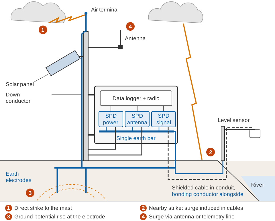
IEC 62305 classifies sources of damage by where the flash lands: on the structure (S1), near it (S2), on a line connected to it (S3), or near such a line (S4) [5]. For a field station this gives four entry paths.
1. Direct strike to the mast. The mast is often the tallest object around, so it attracts the flash. If the current's path to earth runs through the enclosure, the logger or a sensor cable, the result is burnt tracks, exploded components and sometimes fire.
2. Induced surges on long cables. A nearby flash produces a rapidly changing electromagnetic field, the lightning electromagnetic impulse (LEMP). Any loop of conductor in it, such as a 50 m cable to a sensor on a bridge, has a voltage induced in it. Zhang and colleagues measured this at an automatic weather station using rocket-triggered lightning. Return strokes of 6.7–26.5 kA induced main voltage peaks of 5.0–10.3 kV on an overhead power line and 0.4–3.1 kV on the vertical signal cable of a wind sensor. They drove up to 1.6 kA through the surge protector on the power line [3].
3. Ground potential rise. Current flowing into the earth raises the voltage of the soil around the entry point. The Indian earthing code defines earth potential rise as the voltage between an earthing system and reference earth; for a grid it is the current multiplied by the earthing resistance [10]. If the logger is earthed at the mast and the sensor separately at the riverbank, that difference appears across the sensor cable and the logger's inputs.
4. Antenna and telemetry lines. The antenna sits high and its coaxial feed runs straight into the radio, the most sensitive circuit in the station. Wired telemetry and any mains line are entry paths in the same way.
The framework in the standards
IEC 62305 Protection against lightning has four parts: general principles, risk management, physical damage to structures and life hazard, and electrical and electronic systems within structures. IEC published new editions in September 2024 [4]. The Bureau of Indian Standards adopted the 2010 editions as IS/IEC 62305, identical to the IEC text and superseding IS 2309:1989 [5]. Values quoted below are from the Indian adoption of Part 1.
Two ideas organise the series:
- Lightning protection level (LPL), I to IV, fixes the lightning current the protection is designed for. The maximum peak current is 200 kA for LPL I, 75 % of that for LPL II and 50 % for LPL III and IV [5].
- Lightning protection zones (LPZ). LPZ 0A is exposed to direct flashes. LPZ 0B is protected from direct flashes but sees the full electromagnetic field. In LPZ 1, surge currents are limited by current sharing, isolating interfaces or surge protective devices (SPDs) at the boundary [5].
At a station, the air terminal puts the equipment in LPZ 0B, and bonding plus SPDs at the enclosure wall make its inside LPZ 1.
Air terminal and down conductor
An air terminal is a metal rod above everything else on the mast that intercepts the flash. A down conductor carries the current to the earth electrode by a short, direct route outside the enclosure and away from signal cables.
The height is set with the rolling sphere method: imagine a sphere rolled over the station; whatever it can touch can be struck. The radius is 20, 30, 45 and 60 m for LPL I to IV [5].
Worked example (illustrative). A 6 m mast with a 1 m rod puts the tip at h = 7 m. For LPL III, r = 45 m. The protected distance from the rod at height y is:
x(y) = √(2·r·h − h²) − √(2·r·y − y²)

Ground level, y = 0:     x = √(630 − 49)          = 24.1 m
Enclosure at y = 4 m:    x = 24.1 − √(360 − 16)   = 5.5 m
Antenna tip at 6.5 m:    x = 24.1 − √(585 − 42.3) = 0.8 m
An enclosure or panel at 4 m within about 5.5 m of the rod is protected. An antenna tip at 6.5 m is protected only within 0.8 m of it. Keep antennas below the rod tip and close to it.
A single-point earth
The key idea is equipotential bonding: connect every metal part to one reference, so that during a surge everything rises in voltage together. WMO calls equipotential bonding of the different electrical masses, including cable shields, a basic rule for good surge protection. Ground connections should be as short as possible so spikes pass through them rather than the electronics. Where there is no site earth network, a local grounding electrode and buried grounding network must be installed [9].
In a small station that means one earth bar at the enclosure entry. The mast, the electrode, the SPD earth terminals, cable shields and the enclosure all connect to it. Nothing gets its own separate rod.
A separate "clean" earth for the electronics is a mistake, because of ground potential rise.
Worked example (illustrative). The Indian earthing code gives the resistance of a rod electrode as R = (100 ρ / 2π l) · ln(4l / d), with l and d in centimetres and ρ the soil resistivity in Ω·m [10]. In metres:
R = (ρ / 2π L) · ln(4L / d)          rod L = 3 m, d = 16 mm

ρ = 100 Ω·m   →  R = (100 / 18.85) · ln(750) = 5.31 × 6.62 ≈ 35 Ω
ρ = 1000 Ω·m  →  R ≈ 351 Ω

Resistive rise for 10 kA:  V = I · R  →  about 350 kV at 35 Ω
Soil ionisation and conductor inductance change the exact number, but the station's earth still rises by hundreds of kilovolts. A sensor 60 m away on its own rod stays near remote earth, so that voltage appears across its cable. Low resistance helps; what protects the equipment is that everything rises together. Hence the bonding conductor to the sensor post in the diagram.
Illustrative: a single vertical rod in uniform soil, resistive rise only.
Several rods joined by a buried strip lower the resistance. The earthing code notes that resistivity rises very abruptly once soil moisture falls below about 20 %, and that normal soils range from about 10 % moisture in dry seasons to 35 % in wet seasons [10]. An electrode that measures well in August may not in April.
Surge protective devices
An SPD limits transient overvoltages and diverts surge currents, and contains at least one non-linear component [5]. Its voltage-limiting components are of two kinds [7]: switching components stay open until a threshold voltage and then conduct heavily, while clamping components conduct progressively harder as voltage rises. Either way, for the microseconds of the surge the SPD connects the line to the earth bar.
What the label means:
- Test class I, II or III (T1, T2, T3). Class I SPDs are tested with impulse current Iimp of 10/350 µs waveform, representing partial lightning current. Class II with nominal discharge current In of 8/20 µs. Class III with a combination wave [5]. A 10/350 µs impulse rises in 10 µs and falls to half in 350 µs, so it carries far more energy than an 8/20 µs impulse of the same peak.
- Uc, maximum continuous operating voltage: must exceed the highest normal voltage on the line, including a charging battery.
- Up, voltage protection level: the voltage let through during a surge. It must be below the equipment's rated impulse withstand voltage [5].
IS/IEC 62305-1 places Class I or II SPDs at the line entrance and Class I, II or III close to the apparatus, forming a coordinated SPD system [5]. The product standards follow the type of line:
- IEC 61643-11 for AC power circuits up to 1,000 V RMS, such as a mains supply [6].
- IEC 61643-31 for the DC side of photovoltaic generators and inverters up to 1,500 V DC. It states that PV systems with energy storage, such as batteries, are not covered [8], so a battery-backed station needs DC SPDs whose manufacturer data cover that use.
- IEC 61643-21 for telecommunications and signalling networks [7]: sensor buses, analogue loops and wired telemetry.
Annex E of IS/IEC 62305-1 gives the surge current each conductor should be expected to carry. The 2024 edition specifies these more accurately for SPD dimensioning [4], so design with the current edition.
Note the last row: a direct strike to the mast pushes kiloamperes into every conductor, signal cables included, so signal SPDs on an exposed mast must be chosen for that.
WMO adds three practical points. SPDs are often one-shot devices, so they should be easy to replace and show their status visibly. Galvanic isolation does not remove the need for SPDs on digital lines, because high-frequency spikes cross transformers. And the state of the surge protection belongs on every field inspection [9].
Shielded cable and routing
- Use shielded, twisted-pair sensor cable. WMO recommends shielding against capacitive coupling and twisted pairs against electromagnetic coupling [9]. Bond the shield to the earth bar at the entry.
- Bury long runs, in metal conduit where possible; IS/IEC 62305-1 notes that its overhead-line surge currents can be halved for buried lines [5].
- Keep signal cables away from the down conductor and never run them alongside it.
- Bring every cable in at one entry point next to the earth bar, so SPD earth leads are a few centimetres long. A long lead adds its own voltage drop.
- Lay a bonding conductor with the cable to any separate sensor post.
- Consider isolating interfaces. The standard lists metal-free fibre-optic cables and opto-isolators among them [5]. Fibre carries no surge current.
Where surges enter, and what to fit
| Entry point | How the surge arrives | Protection |
|---|---|---|
| Mast top | Direct strike (S1) | Air terminal above all equipment, placed by rolling sphere; down conductor outside the enclosure |
| Solar panel cable | Partial lightning current; induction in the panel loop | Panel frame bonded to mast; DC SPD at the enclosure entry |
| Battery and charge controller | Surges on panel or load lines | DC SPDs at the entry, short leads to the earth bar |
| Mains supply, if any | Flash to or near the line (S3, S4) | Class I or II SPD to IEC 61643-11; buried service cable |
| Sensor cable | Induction (S2, S4); potential difference between earths | Shielded twisted pair in buried conduit; IEC 61643-21 SPD; bonding conductor to sensor post; fibre for long runs |
| Antenna and coax | Strike to the mast; field coupling | Antenna below the rod tip; shield bonded at entry; coaxial protector for the radio band |
| The earth | Ground potential rise | One bonded earth system; no separate "clean" earth |
Testing the earth
The Indian earthing code describes the fall-of-potential method: current is passed between the electrode and a remote current probe, and the voltage to a potential probe gives R = V / I. For small systems the recommended version is the 61.8 % test, with the potential probe at 61.8 % of the distance to the current probe, then moved to 50 % and 70 % to confirm. For a rod, the current probe should be at least 30 m away; 50 m is usually adequate for smaller systems [10].
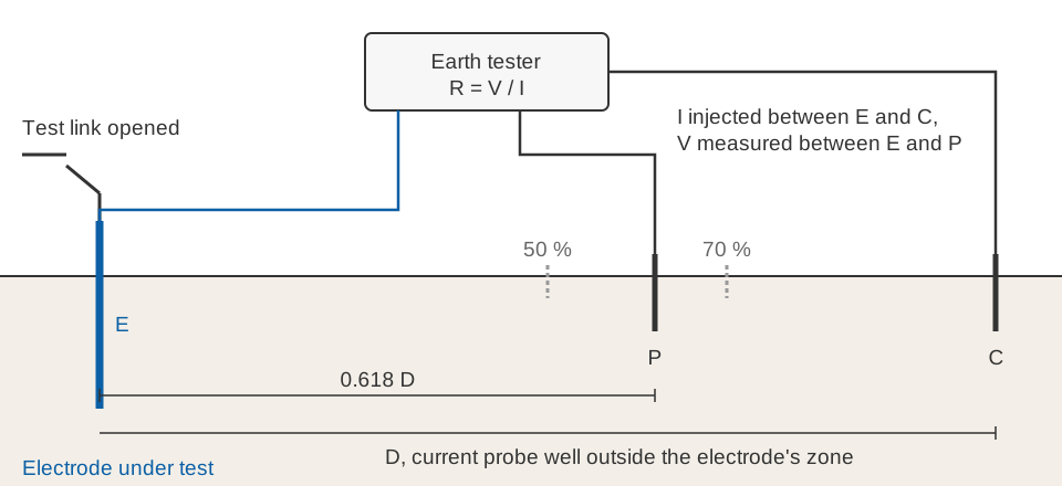
- Fit a test link so the electrode can be separated from the station during the test, as the code asks where possible [10].
- Measure soil resistivity before building, by the Wenner four-electrode method the code recommends [10], to know how many rods you need.
- Record every reading with date and soil condition; the code recommends periodic tests with records kept [10]. A dry-season test gives the worst case.
- Inspect after every storm season: joints, clamp corrosion, SPD indicators and cable entries.
Key points
- Most damage at remote stations comes from surges, not direct hits: induction on long cables, potential differences between separate earths, and surges on antenna and power lines.
- IEC 62305, adopted in India as IS/IEC 62305, provides protection levels, protection zones, the rolling sphere and the coordinated SPD system.
- Place the air terminal by rolling sphere and keep antennas below its tip.
- Bond everything to one earth. Potential rise of hundreds of kilovolts cannot be avoided, but it can act on the whole station at once.
- Choose SPDs by line type (IEC 61643-11, 61643-31, 61643-21), test class, Uc and Up, and mount them at one entry with short earth leads.
- Measure the earth by fall of potential, keep records, and check SPDs every season.
ClimMaTech's monitoring devices, including Tarang, each have an integrated data logger, and the earthing, cable entries and surge protection described here apply to the field stations they are installed in. Our RTDAS hydromet telemetry solution links such stations to a central system, which makes the antenna and telemetry line one of the entry points to protect. For related design choices, see telemetry link design for hydromet stations and the guide to automatic river water level recorders.
References
- K. Prasanna, V. Gopalakrishnan, S. D. Pawar, Trends of lightning flash density over India during different seasons, International Journal of Climatology 44(5), 1587–1610, 2024. doi.org/10.1002/joc.8400
- National Disaster Management Authority, Government of India, Guidelines for Preparation of Action Plan – Prevention and Management of Thunderstorm & Lightning / Squall / Dust / Hailstorm and Strong Winds, NDMA, 2018 (sections 1.2 and 4.3(b)). Copy hosted by Gujarat Institute of Disaster Management
- Y. Zhang, S. Chen, D. Zheng, W. Lu, B. Li, Experiments on lightning protection for automatic weather stations using artificially triggered lightning, IEEJ Transactions on Electrical and Electronic Engineering 8(4), 313–321, 2013. doi.org/10.1002/tee.21861
- International Electrotechnical Commission, IEC 62305 Protection against lightning, Part 1: General principles; Part 3: Physical damage to structures and life hazard; Part 4: Electrical and electronic systems within structures, edition 3.0, IEC, 2024. Part 1, Part 3, Part 4
- Bureau of Indian Standards, IS/IEC 62305-1:2010 Protection Against Lightning, Part 1: General Principles (identical with IEC 62305-1:2010; supersedes IS 2309:1989), BIS, 2015. archive.org (archived copy)
- International Electrotechnical Commission, IEC 61643-11:2025 Low-voltage surge protective devices – Part 11: Surge protective devices connected to AC low-voltage power systems – Requirements and test methods, IEC, 2025. webstore.iec.ch/en/publication/65314
- International Electrotechnical Commission, IEC 61643-21:2025 Low-voltage surge protective devices – Part 21: Surge protective devices connected to telecommunications and signalling networks – Requirements and test methods, IEC, 2025. webstore.iec.ch/en/publication/69085
- International Electrotechnical Commission, IEC 61643-31:2018 Low-voltage surge protective devices – Part 31: Requirements and test methods for SPDs for photovoltaic installations, IEC, 2018. webstore.iec.ch/en/publication/26931
- World Meteorological Organization, Guide to Instruments and Methods of Observation, Volume III – Observing Systems, WMO-No. 8, 2024 edition, Chapter 1 (sections 1.3.3–1.3.6 and field inspections). WMO publication page
- Bureau of Indian Standards, IS 3043:2018 Code of Practice for Earthing (Second Revision), BIS, 2018 (sections 3.25, 10.1, 13.6, 14.2.2, 38, 40 and 41). archive.org (archived copy)