
Modbus RTU explained: registers, function codes, pitfalls
How a Modbus RTU request and response are built byte by byte, what the four data tables and eight common function codes do, and the mistakes that most often turn a good sensor reading into a wrong number.

A water level sensor is wired to the logger, the bus looks healthy, and the logger is polling. Yet the value on the screen is 4.07 × 10²⁹ metres, or it is stuck at zero, or it is exactly ten times too small. In almost every such case the wiring is fine and the problem is in the protocol: the wrong register, the wrong word order, a missing scale factor, or a timeout set for a different device. This article explains Modbus RTU from the ground up, so that you can read a device's register map, check a frame by hand and recognise these faults quickly.
The physical layer, RS-485 wiring, termination and biasing, is covered in a separate article: SDI-12 and RS-485, the two sensor buses hydromet stations rely on. Here we deal only with the protocol.
Two specifications, two layers
Modbus is defined by two documents from the Modbus Organization. The application protocol specification describes what is exchanged: the data model, the function codes and the exception responses [1]. The serial line specification describes how those messages travel over a serial bus: addressing, framing, timing and error checking [2]. Modbus RTU (Remote Terminal Unit) is one of the two serial transmission modes in the second document. The other, Modbus ASCII, sends each byte as two text characters; RTU packs two hexadecimal digits into each byte and so moves more data at the same baud rate [2].
Data is big-endian inside a register: for a 16-bit value of 0x1234, the byte 0x12 is sent first, then 0x34 [1]. Keep that in mind; it matters later.
Master and slave, client and server
On a Modbus serial line there is exactly one master (the device that asks, usually the data logger or a PLC) and up to 247 slaves (the sensors or instruments that answer). The serial specification uses master and slave; the application specification uses the equivalent terms client and server, and states that on a serial line the master acts as client and the slaves as servers [2]. We use client and server below.
The rules that follow from this model are simple and strict [2]:
- Only the client starts a transaction. A server never transmits unless asked, and servers never talk to each other.
- The client has one transaction in progress at a time.
- Each server has an address from 1 to 247, and that address must be unique on the bus. Addresses 248 to 255 are reserved.
- Address 0 is broadcast. Every server must accept it, broadcasts may only be write commands, and no server replies to one.
The RTU frame
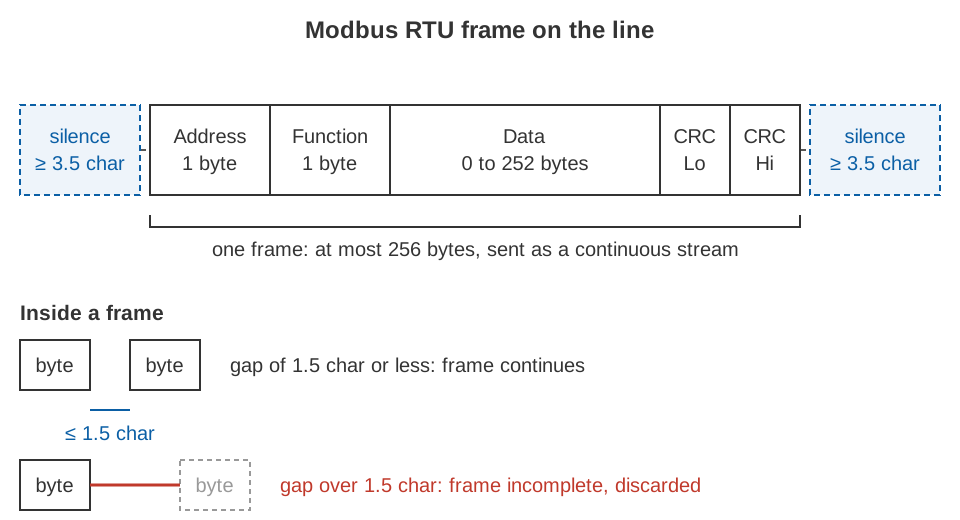
Every RTU message, request or response, has the same four parts [2]:
| Field | Size | Contents |
|---|---|---|
| Address | 1 byte | Server address (1–247, or 0 for broadcast). In a response, the server's own address. |
| Function code | 1 byte | What to do: read coils, write a register and so on. |
| Data | 0 to 252 bytes | Starting address, quantity, values, byte count, depending on the function. |
| CRC | 2 bytes | Error check, low byte first. |
The maximum RTU frame is therefore 256 bytes, and the protocol data unit (function code plus data) is at most 253 bytes [1][2].
Each byte travels as an 11-bit character: one start bit, eight data bits sent least significant bit first, one parity bit and one stop bit. Even parity is the required default; odd parity and no parity are allowed, but no parity requires two stop bits so that every character stays 11 bits long [2].
Silent intervals: how a receiver finds a frame
RTU has no start-of-message or end-of-message character. Frames are separated by silence [2]:
- A frame must be preceded and followed by a silent interval of at least 3.5 character times (called t3.5).
- Inside a frame, the bytes must form a continuous stream. If a gap of more than 1.5 character times (t1.5) occurs between two bytes, the receiver declares the frame incomplete and should discard it.
A character time is the time to send one 11-bit character, so it depends on the baud rate:
character time = 11 bits / baud rate
t1.5 = 1.5 × character time
t3.5 = 3.5 × character time

At 9600 baud:  character time = 11 / 9600 = 1.146 ms
               t1.5 = 1.72 ms     t3.5 = 4.01 ms
The specification says these two timers must be strictly respected at 19,200 baud and below. Above 19,200 baud, where they become very short and would load the processor with interrupts, fixed values are recommended: 750 µs for t1.5 and 1.750 ms for t3.5 [2]. Every device must support 9600 and 19,200 baud, and 19,200 baud is the required default [2].
The CRC: a check on every byte
The last two bytes of each frame are a cyclic redundancy check (CRC-16), computed over the address, function code and data. The receiver recalculates it and discards the frame if the two values differ. Only the eight data bits of each character take part; start, parity and stop bits do not [2]. The procedure in the specification is [2]:
1. Load a 16-bit register with 0xFFFF.
2. XOR the next message byte into the low byte of the register.
3. Shift the register one bit to the right, filling the top bit with 0.
4. If the bit shifted out was 1, XOR the register with 0xA001.
5. Repeat steps 3 and 4 until eight shifts are done.
6. Repeat steps 2 to 5 for every byte of the message.
7. The register now holds the CRC. Send its LOW byte first, then its HIGH byte.
The constant 0xA001 is the bit-reversed form of the generator polynomial 1 + x² + x¹⁵ + x¹⁶ [2]. Step 7 is the one most often got wrong when people write their own code: the CRC is the only field in a Modbus frame that is sent low byte first.
The data model: four tables
The application specification organises everything a server exposes into four primary tables [1]:
| Table | Object | Access | Typical use at a station |
|---|---|---|---|
| Discrete inputs | 1 bit | Read only | A door switch, a float switch, a fault flag |
| Coils | 1 bit | Read and write | A relay output, a pump or siren enable |
| Input registers | 16-bit word | Read only | Measured values: level, flow, battery voltage |
| Holding registers | 16-bit word | Read and write | Settings, and on many devices measured values too |
Each table can hold up to 65,536 items, addressed in a request from 0 to 65,535 [1]. The specification also notes that the tables may overlap inside a device; the split between inputs and outputs, bits and words, implies no particular behaviour [1]. Which register holds which quantity is entirely up to the manufacturer and is given in the device's register map.
Function codes
The function code tells the server what to do. These eight cover nearly all hydromet work [1]:
| Code | Name | Table | Limit per request |
|---|---|---|---|
| 01 (0x01) | Read Coils | Coils | 1 to 2000 coils |
| 02 (0x02) | Read Discrete Inputs | Discrete inputs | 1 to 2000 inputs |
| 03 (0x03) | Read Holding Registers | Holding registers | 1 to 125 registers |
| 04 (0x04) | Read Input Registers | Input registers | 1 to 125 registers |
| 05 (0x05) | Write Single Coil | Coils | One coil: 0xFF00 = ON, 0x0000 = OFF |
| 06 (0x06) | Write Single Register | Holding registers | One register |
| 15 (0x0F) | Write Multiple Coils | Coils | 1 to 1968 coils |
| 16 (0x10) | Write Multiple Registers | Holding registers | 1 to 123 registers |
Note that function 05 does not accept 0x0001 for ON. Any value other than 0xFF00 or 0x0000 is illegal and does not change the output [1].
Exception responses
If a server receives a valid frame but cannot carry out the request, it returns an exception response: the original function code with its top bit set (function code + 0x80), followed by one exception code [1]. The four you will see most are:
| Code | Name | Usual meaning in the field |
|---|---|---|
| 01 | Illegal function | The device does not support this function code. |
| 02 | Illegal data address | The starting address plus quantity reaches a register that does not exist. |
| 03 | Illegal data value | A value in the request is not allowed, for example a quantity out of range. |
| 04 | Server device failure | An unrecoverable error occurred while the server was carrying out the request. |
Gateways use 0x0A (path unavailable) and 0x0B (target device failed to respond) [1]. An exception is good news in one sense: the wiring, baud rate, parity and address are all correct, because the server heard you and answered. If there is no response at all, look at those first.
Worked example: read two holding registers
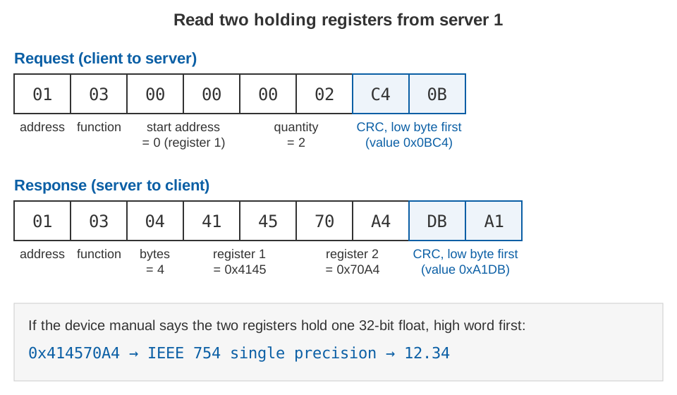
Suppose the register map of a level sensor at address 1 says: holding registers 1 and 2, water level as a 32-bit float, high word first. The logger sends function 03 with starting address 0 (register 1 is address 0, see the next section) and quantity 2.
Request (client to server)
01         server address 1
03         function: Read Holding Registers
00 00      starting address 0x0000
00 02      quantity 2 registers
C4 0B      CRC = 0x0BC4, low byte first

Full frame: 01 03 00 00 00 02 C4 0B
The server replies with the same address and function code, a byte count of 4 (two registers × two bytes), the register contents and its own CRC:
Response (server to client)
01         server address 1
03         function: Read Holding Registers
04         byte count
41 45      register 1 = 0x4145
70 A4      register 2 = 0x70A4
DB A1      CRC = 0xA1DB, low byte first

Full frame: 01 03 04 41 45 70 A4 DB A1
Both CRCs were computed with the procedure above; you can check them with any Modbus CRC routine. Putting the high word first gives the 32 bits 0x414570A4. Read as an IEEE 754 single-precision float [3] (1 sign bit, 8 exponent bits with a bias of 127, 23 fraction bits):
0x414570A4 = 0 | 10000010 | 10001010111000010100100
sign     = 0                      (positive)
exponent = 130 − 127 = 3
fraction = 1 + 0x4570A4 / 2^23 = 1.5425
value    = 1.5425 × 2^3 = 12.34
If register 1 did not exist, the server would instead return 01 83 02 C0 F1: function 0x83 (0x03 + 0x80), exception code 02, illegal data address, and the CRC.
Common pitfalls
1. Zero-based addresses and the 40001 notation
The specification numbers elements in each table from 1 to n, but in the request itself element X is addressed as X − 1: holding register 1 is sent as address 0, and registers 108 to 110 are read with starting address 107 (0x006B) [1]. Many register maps add a further layer: they write holding registers with a leading 4, so "40001" means holding register 1, and input registers with a leading 3, so "30001" means input register 1. That prefix is a documentation convention that only names the table; it is not part of the current specification and is never sent on the wire. The table is chosen by the function code.
So "40001" in a manual becomes function 03, address 0x0000. If the manual instead lists "register address 0", it may already be zero-based. When a value looks plausible but wrong, read one register either side; an off-by-one error usually shows itself as a neighbouring parameter.
2. 32-bit values and word order
A register holds 16 bits. The specification defines the byte order within a register (big-endian) but says nothing about how two registers combine into a 32-bit integer or float [1]. Manufacturers differ. With the bytes A B C D from the example above, four orders are in use:
| Name | Byte order | Value from 41 45 70 A4 |
|---|---|---|
| Big-endian (high word first) | A B C D | 12.34 |
| Word swap (low word first) | C D A B | 4.07 × 10²⁹ |
| Byte swap within words | B A D C | 3098.28 |
| Little-endian | D C B A | −5.21 × 10⁻¹⁷ |
A wildly large or tiny float is almost always a word-order error. Try the decoder below with your own register values.
3. Scaling, units and signed values
Many devices send integers with an implied scale, for example a level in millimetres, or a value × 100. A raw register of 1234 is 1.234 m at a scale of 0.001 and 12.34 at a scale of 0.01. The register map gives the factor; the protocol does not. Check also whether a register is signed: 0xFFF6 is 65,526 as an unsigned integer and −10 as a signed (two's complement) one. A temperature or a level relative to a datum can legitimately be negative.
4. Timeouts and retries
After a request, the client waits for a response time-out. Its value is left to the application, and the specification gives 1 s to several seconds at 9600 baud as typical. If a frame arrives with an error, the client may retry; if nothing arrives, the time-out expires and the client may retry up to a number set in its configuration [2]. Both settings cost time. With a 1 s time-out and two retries, one silent sensor blocks the bus for 3 s on every polling cycle, and readings from every other device on that bus are delayed with it. Set the time-out from the slowest device's documented response time with a margin, not from habit, and log time-outs per device so that a failing sensor shows up as a trend rather than as gaps.
5. Polling rate
A transaction takes longer than people expect. An illustrative calculation at 9600 baud with 11-bit characters, for the 8-byte request and 9-byte response above, assuming the sensor takes 20 ms to prepare its answer:
request   8 × 1.146 ms = 9.2 ms
response  9 × 1.146 ms = 10.3 ms
silence   2 × 4.0 ms   = 8.0 ms
device    (assumed)      20 ms
total                  ≈ 47.5 ms per transaction
That is about 20 transactions per second at best. Ten sensors with three requests each take about 1.4 s per cycle, before any retries. Read contiguous registers in one request rather than one at a time, and poll each device no faster than its value actually changes.
6. Parity and stop-bit mismatch
Baud rate, parity and stop bits must match on every device on the bus. The required default is even parity, and devices set to no parity must use two stop bits [2]. A device set to no parity and one stop bit does not follow that rule, so check the manual's serial settings rather than assuming them. A parity mismatch can look like an intermittent fault, because some bytes pass by chance, so check the serial settings first when CRC errors appear at random.
7. Duplicate addresses
Two servers with the same address both answer the same request. Their replies collide on the shared pair and the client sees garbage, CRC errors or nothing, while each device works perfectly on its own. The specification requires every address on a bus to be unique [2]. Identical devices delivered with the same default address will clash as soon as two of them share a bus, so set and label each one before it goes on the bus, and keep the address list with the station records.
Key points
- Modbus RTU is a client–server (master–slave) protocol: one client asks, up to 247 servers at addresses 1–247 answer, and address 0 is a broadcast with no reply.
- An RTU frame is address, function code, data and a CRC-16 sent low byte first, separated from other frames by at least 3.5 character times of silence; a gap over 1.5 character times inside a frame invalidates it.
- Character time is 11 bits divided by the baud rate; above 19,200 baud the specification recommends fixed timers of 750 µs and 1.75 ms.
- The four tables are coils, discrete inputs, input registers and holding registers; functions 01–06, 15 and 16 read and write them, and an exception response sets the top bit of the function code.
- Most field errors come from off-by-one addressing, 32-bit word order, missing scale factors, poorly set time-outs, serial setting mismatches and duplicate addresses, not from the protocol itself.
Much of the work of commissioning a station is exactly what this article describes: reading each register map carefully and checking each value against a known reading before it enters the record. It is part of how we set up our RTDAS and hydromet telemetry networks.
References
- Modbus Organization, MODBUS Application Protocol Specification V1.1b3, Modbus Organization, 2012. modbus.org (listed at modbus.org/modbus-specifications).
- Modbus Organization, MODBUS over Serial Line Specification and Implementation Guide V1.02, Modbus Organization, 2006. modbus.org.
- IEEE, IEEE 754-2019, IEEE Standard for Floating-Point Arithmetic, IEEE Standards Association, 2019. standards.ieee.org.