
SDI-12 and RS-485: the two sensor buses hydromet stations rely on
How the two common wired sensor buses work, how far and how many they reach, how they compare with a 4–20 mA loop, and the wiring and addressing mistakes that cause most field faults.

A river or weather station is rarely one sensor. A level sensor on a bridge, a rain gauge on a mast and perhaps a water quality probe all have to get their readings to a data logger over cables tens of metres long, through monsoon storms and electrical noise. When a station sends gaps, garbage or the same value for three days, the fault is often in that cable rather than in the sensor.
Two digital buses carry most of these readings: SDI-12 and RS-485. Both let several sensors share one cable, but they are built on very different ideas. This article explains each, compares them with the analogue 4–20 mA loop, and lists the wiring and addressing mistakes we see most often.
A few terms first. A bus is a shared cable to which several devices connect. The master (here, the data logger) starts every conversation; the sensors only answer. A baud rate is the number of signal symbols per second; for both buses discussed here, one symbol is one bit.
SDI-12: a slow, frugal bus made for sensors
SDI-12 stands for "serial/digital interface at 1200 baud". It was designed for battery-powered data recorders reading microprocessor-based environmental sensors, with minimal current drain and low system cost [1]. The specification is maintained by the SDI-12 Support Group; the current version is 1.4 [1].
Three wires
The SDI-12 bus is a cable with three conductors: a serial data line, a ground line and a 12-volt line [1].
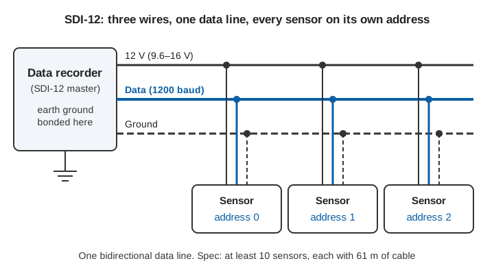
- Data line. One wire carries data in both directions, in turn. It uses negative logic: a binary 1 ("marking") is −0.5 to 1.0 V and a binary 0 ("spacing") is 3.5 to 5.5 V [1]. Each device's transmitter has a source resistance of 1,000 to 2,000 Ω, so the maximum cable length depends on the total capacitance of all cables on the data line [1].
- 12 V line. The recorder or an external supply provides 9.6 to 16 V, measured under a maximum sensor load of 0.5 A [1]. The recorder does not have to be the source of this power.
- Ground line. It is connected to circuit ground and earth ground at the data recorder. Sensor circuit grounds connect to it, but not normally to their own earth. The ground conductor should be heavy enough to keep the voltage drop between recorder and sensors below 0.5 V at the maximum combined sensor current [1].
The specification states that the bus can have at least 10 sensors, each with 200 feet (about 61 m) of cable, and that longer cables are possible with fewer sensors [1]. It also recommends transient protection on the bus [1], which matters at stations exposed to lightning in the monsoon.
Characters and addresses
Data are sent as ASCII characters at 1200 baud, each framed as 1 start bit, 7 data bits, 1 even-parity bit and 1 stop bit [1]: ten bits per character, so one character takes 10 / 1200 s = 8.33 ms.
Every command starts with a one-character address, and every response starts with the same address, so the recorder can check who answered. All sensors leave the factory set to address 0. The addresses 0 to 9 must be supported by every sensor and recorder; for more than 10 sensors, the letters A–Z and a–z can be used [1].
The basic commands
All version 1.4 sensors and recorders must support the basic commands [1]. The ones you will use most (with a standing for the address):
| Command | Name | Response | What it does |
|---|---|---|---|
a! | Acknowledge active | a | "Are you there?" |
?! | Address query | a | Any sensor answers with its address, so connect only one |
aI! | Send identification | allccccccccmmmmmmvvvxxx… | SDI-12 version, 8-character vendor, 6-character model, 3-character sensor version, optional serial (up to 13 characters) |
aAb! | Change address | b | Changes the address from a to b (if the sensor supports it) |
aM! | Start measurement | atttn | Sensor needs ttt seconds and will return n values (1–9) |
aC! | Start concurrent measurement | atttnn | As M, up to 99 values, while other sensors measure too |
aD0! … aD9! | Send data | a<values> | Returns the values, e.g. 0+3.14+2.718 |
Every response ends with carriage return and line feed (CR LF). Values are sent as a sign followed by digits and an optional decimal point [1]. An M measurement may return at most 35 characters in its values field, for compatibility with older recorders, while a C measurement may return up to 75 [1].
Timing
SDI-12 sensors sleep between readings. The recorder wakes them with a break: the data line held at spacing for at least 12 ms. The recorder then holds marking for 8.33 ms and sends the command. The addressed sensor answers, and the start bit of its first character must begin within 15 ms of the end of the command [1]. A sensor may take up to 100 ms to wake after a break, goes back to sleep after 100 ms of idle line, and a new break is needed when the recorder addresses a different sensor or the line has been idle for more than 87 ms [1]. Because a sensor may not yet be awake for the first try, the recorder must support retries, with at least one retry sent more than 100 ms after the break [1].
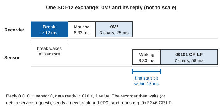
Worked example (illustrative). A logger reads a level sensor at address 0:
Recorder: break, then 0M!          3 characters x 8.33 ms = 25 ms
Sensor:   0 010 1 CR LF            7 characters x 8.33 ms = 58 ms
          (address 0, ready in 010 s, 1 value)
... recorder waits up to 10 s, or until the sensor sends a service request ...
Recorder: break, then 0D0!         4 characters = 33 ms
Sensor:   0+2.346 CR LF            9 characters = 75 ms
The traffic on the wire takes well under half a second; the 10 s is the sensor's own measuring time. With aC!, the recorder can start a concurrent measurement on sensor 0, go on to start sensor 1, and collect both afterwards, which saves time on a bus with several slow sensors [1].
RS-485: a fast, rugged differential pair
RS-485 (formally TIA/EIA-485-A) is a different kind of standard. It defines only the electrical characteristics of drivers and receivers for a balanced, multipoint line [2][3]. It says nothing about characters, commands or power, which is why it is always paired with a protocol on top.
Differential signalling
Instead of one wire measured against ground, RS-485 sends each bit as the difference between two wires, A and B. A standard driver produces at least 1.5 V across a 54 Ω load, and a standard receiver detects a difference down to 200 mV [3]. Noise from external sources such as a nearby power cable couples almost equally into both wires of a twisted pair, so it appears as common-mode voltage (the same on both wires), which the receiver rejects [3]. The receiver must keep working while the common-mode voltage on the bus lies between −7 V and +12 V [3][4]. This is the main reason RS-485 tolerates long cables in noisy places.
Half-duplex multi-drop
Hydromet stations almost always use the half-duplex form: one twisted pair, shared by all nodes, with data flowing one way at a time. Only one driver may be active at any moment; if two drive the bus together (bus contention) the data are corrupted, and avoiding this is the job of the software [3][4]. A full-duplex form with two pairs also exists [3].
Unit loads
The standard limits how many devices the bus can carry through the unit load (UL), a load of roughly 12 kΩ. A compliant driver must be able to drive 32 unit loads [3]. Many modern transceivers present only a fraction of a unit load, such as 1/8 UL, allowing up to 256 devices [3].
Termination and stubs
At higher data rates the cable behaves as a transmission line, and signals reflect from any impedance mismatch. Industrial RS-485 cable is twisted pair with a characteristic impedance of 120 Ω, so the trunk is terminated with a 120 Ω resistor at each of the two ends of the cable, and the short branches to each device (stubs) are kept as short as possible [3]. The standard suggests a daisy-chain (bus) topology, with devices joined to the main cable by short stubs [3].
Fail-safe biasing
When no driver is active, which is most of the time on a polled bus, the two wires float at nearly the same voltage, and a receiver's output can become random. Fail-safe circuits force a defined state. Many transceivers have them built in, but their worst-case noise margin can be as small as 10 mV, so noisy installations add an external bias network: a resistor pulling one line up and another pulling the other line down, which holds the idle differential voltage above the 200 mV threshold [3]. The design guide's example uses two 523 Ω resistors with a 5 V supply [3]. The bias network itself adds up to 20 unit loads [3].
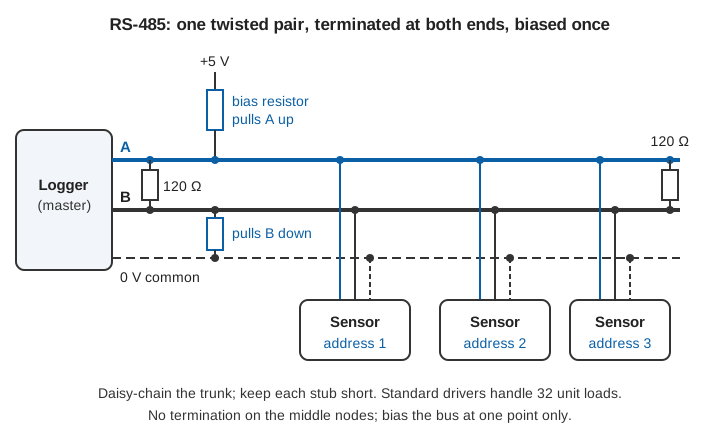
Worked example: the node budget. With 1/8-UL transceivers and an external bias network [3]:
N = (32 UL − 20 UL for bias) / (1/8 UL per transceiver) = 96 devicesA simple check of the bias, ignoring receiver loading: the two 120 Ω terminations in parallel give 60 Ω between A and B, so with a 4.75 V supply (5 V − 5 %) and two 523 Ω bias resistors, the idle differential voltage is 4.75 × 60 / (523 + 60 + 523) ≈ 0.26 V, just above the 0.25 V the design guide targets (200 mV threshold plus 50 mV noise allowance) [3].
Cable length and data rate
The headline figures usually quoted for RS-485 are 10 Mbit/s over about 12 m (40 ft) and about 1,200 m (4,000 ft) at 100 kbit/s [3]. In between, a conservative rule of thumb is that cable length in metres times data rate in bit/s should stay below 10⁷; at low data rates the limit is set instead by cable resistance, which for 22 AWG twisted pair reaches the point of halving the signal at roughly 1,200 m [3].
| Data rate | Length from the 10⁷ rule | Practical guide |
|---|---|---|
| 9,600 bit/s | 1,042 m | about 1,000 m |
| 19,200 bit/s | 521 m | about 500 m |
| 115,200 bit/s | 87 m | under 100 m |
The rule is deliberately cautious; the design guide notes that real cables do better [3].
Grounding: "two wires" is not the whole story
RS-485 is often drawn with only two wires, but a remote node and the logger may sit at different ground potentials, and that difference adds to the common-mode voltage. If it pushes the bus outside −7 V to +12 V, the link fails [3]. Connecting the remote grounds directly lets ground-loop currents flow, so the standard recommends some resistance between logic ground and chassis ground, and galvanic isolation is the robust answer when ground differences can reach kilovolts [3][4]. In practice: run a third conductor as a 0 V reference, connect it as the standard intends, and use isolated transceivers where the sensor and logger are powered or earthed separately, for example a sensor on a bridge and a logger in a hut on the bank.
A note on Modbus
Because RS-485 defines only the electrical layer, a protocol is needed on top. A common choice in hydromet stations is Modbus RTU: the logger (master) polls each sensor by its address, reads numbered registers, and checks each message with a CRC. Registers, function codes and the common pitfalls are covered in Modbus RTU explained.
SDI-12, RS-485 and 4–20 mA compared
| SDI-12 | RS-485 (half-duplex) | 4–20 mA loop | |
|---|---|---|---|
| Conductors | 3: data, ground, 12 V [1] | 2 (A, B) plus a 0 V reference [3][4]; power separate | 2 per sensor, carrying power and signal [5] |
| Signalling | Single-ended, 0–5 V, negative logic [1] | Differential, ≥ 1.5 V driven, 200 mV threshold [3] | Analogue current [5] |
| Data rate | 1200 baud, fixed [1] | Set by the protocol; up to 10 Mbit/s on short runs [3] | Continuous analogue value |
| Cable length | At least 10 sensors × 61 m each; longer with fewer sensors [1] | About 1,200 m at low rates [3] | Limited by loop voltage drop [5] |
| Devices per bus | 10 standard addresses, up to 62 with letters [1] | 32 UL; up to 256 with 1/8-UL parts [3] | One sensor per loop |
| Power to sensors | 9.6–16 V on the bus [1] | Not defined by the standard [3] | From the loop itself [5] |
| Noise immunity | Single-ended; edges slowed to ≤ 1.5 V/µs [1] | High, by common-mode rejection [3] | High [5] |
| Typical use | Low-power environmental sensors, battery loggers | Faster sensors, cameras and radars, longer runs | One critical analogue value, legacy and PLC inputs |
| Information sent | Several values per sensor, plus identity | Many values, status and configuration | One value only |
When 4–20 mA is still the better choice
A 4–20 mA loop sends a single measurement as a current: 4 mA for the bottom of the range and 20 mA for the top. Because current is the same everywhere in the loop, wire resistance does not change the reading as long as the supply can overcome the voltage drop; current loops have inherent noise immunity; the 4 mA "live zero" makes a broken wire (0 mA) easy to detect; and a two-wire transmitter can be powered from the loop itself [5].
Choose 4–20 mA when:
- there is one critical value per sensor and you do not need identification, diagnostics or several parameters;
- the receiving equipment is a PLC, SCADA or legacy logger with analogue inputs only;
- you want wire-break detection without any software;
- one faulty sensor must not be able to block a shared bus, because each sensor has its own pair.
The price is one pair and one value per sensor, plus the uncertainty of the analogue chain; a digital bus sends the number exactly as the sensor computed it.
Common wiring and addressing mistakes in the field
On SDI-12
- Two sensors with the same address. Every sensor leaves the factory at address
0[1]. Connect them one at a time, use?!to read the address andaAb!to change it, and label the cable. - Too little time for the sensor. Loggers that do not retry, or that read data before
ttthas elapsed, report intermittent "no response". The specification requires retries [1]. - Voltage drop on long cables. A thin ground or 12 V conductor on a long run, with several sensors measuring at once, can push the ground difference above the 0.5 V the specification allows [1].
- No surge protection on cables that leave the enclosure, despite the specification's recommendation [1].
On RS-485
- Termination in the wrong places: missing, fitted on every device, or fitted at a device in the middle of the line. Fit 120 Ω at the two physical ends of the trunk only [3].
- Star wiring or long stubs, which cause reflections [3]. Daisy-chain the cable from device to device.
- No bias, or bias at several points. A floating idle bus gives random characters; bias added at every node adds unit loads [3].
- A and B swapped. Swapping the two wires inverts every bit. If one device never answers, check its polarity before anything else.
- No 0 V reference, or grounds joined carelessly, leading to ground-potential differences beyond the common-mode range or to ground loops [3][4].
- Two devices with the same address, or mismatched serial settings (data rate, parity, stop bits). Both look like a dead sensor.
- Too many devices for the unit-load budget once bias networks are counted [3].
On both
- Water in junction boxes. Corroded terminals add resistance and leakage paths, which show up first as intermittent errors.
- No record of which sensor is on which address, cable and logger channel. Write it on a label in the enclosure and in the station's documentation. See the AWLR and AWVLR guide for how sensors, loggers and telemetry fit together at a river gauging station.
Key points
- SDI-12 uses three wires (data, ground, 12 V), 1200 baud and single-character addresses; the specification supports at least 10 sensors on 61 m of cable each.
- Its basic commands (
a!,aI!,aM!,aC!,aD0!) are the same for every compliant sensor, which makes sensors interchangeable at the logger. - RS-485 is a differential, half-duplex, multi-drop pair: 32 unit loads, −7 V to +12 V common-mode range, about 1,200 m at low data rates.
- Terminate RS-485 at both ends only, bias it at one point, keep stubs short and carry a 0 V reference.
- RS-485 needs a protocol on top, most often Modbus RTU.
- 4–20 mA remains the right choice for a single critical value, analogue-only receivers and wire-break detection without software.
Getting the bus right is a large part of making a station reliable. ClimMaTech's Tarang radar level sensor, an automatic water level recorder (AWLR), provides SDI-12, RS-485 and 4–20 mA outputs, and like all our monitoring devices it has an integrated data logger. When we design and commission stations, the wiring, addressing and grounding practices in this article are the ones we apply.
References
- SDI-12 Support Group (Technical Committee), SDI-12: A Serial-Digital Interface Standard for Microprocessor-Based Sensors, Version 1.4, SDI-12 Support Group, River Heights, Utah, 2023 (20 February 2023 edition). sdi-12.org.
- Telecommunications Industry Association, TIA-485-A: Electrical Characteristics of Generators and Receivers for Use in Balanced Digital Multipoint Systems, TIA, 1998. Standard listing.
- T. Kugelstadt, The RS-485 Design Guide, Application Report SLLA272D, Texas Instruments, 2008 (revised 2021). ti.com.
- M. Soltero, J. Zhang, C. Cockril, K. Zhang, C. Kinnaird, T. Kugelstadt, RS-422 and RS-485 Standards Overview and System Configurations, Application Report SLLA070D, Texas Instruments, 2002 (revised 2010). ti.com.
- Texas Instruments, 4- to 20-mA Current Loop Transmitter Reference Design, user guide TIDUAM6, 2015, section "System Design Theory". ti.com.