
How FMCW radar measures water level: chirps, beat frequency, phase and the installed error budget
How a radar that never touches the river reaches millimetre precision, what limits it in the field, and why the accuracy on the datasheet is not the accuracy of the installed station.
Measuring a river sounds simple: find out how high the water is. In practice, most traditional methods put something in the water, or right beside it. A float, a pressure cell, a staff gauge someone has to read. In a flood, that is exactly where things go wrong. Debris, silt and fast water damage or foul whatever is in the river, and nobody can safely reach it to fix it.
Radar level sensing takes a different approach. The sensor sits above the water and never touches it. This article explains how that works at the level an engineer needs: how a radar turns an echo into a distance, why that distance can be good to a millimetre, and what else has to be right before the station is as accurate as the sensor.
From echo to distance: time of flight
A radar mounted over the water sends a radio wave down. The wave reflects off the surface and returns. The round-trip time t gives the distance, d = c · t / 2, with c the speed of light. The water level is the height of the sensor above a datum minus d.
The numbers show why this is hard. A millimetre of distance is a round-trip time of about 6.7 picoseconds. Timing a single pulse to that precision is not practical for a low-power field instrument, so level radars use a different idea.
FMCW: turning time into frequency
FMCW stands for frequency-modulated continuous wave. Instead of one short pulse, the radar transmits a signal whose frequency rises steadily over a time Tc, sweeping a bandwidth B. This is called a chirp, and its slope is S = B / Tc. A Texas Instruments introduction to millimetre-wave sensing describes it as a signal whose frequency increases linearly with time, with the reflected chirp being a time-delayed copy of the transmitted one [1].
Because the echo is delayed by τ = 2d / c, at any instant the received frequency lags the transmitted frequency by S · τ. The radar mixes the two signals, and the result is a steady tone, the beat or intermediate frequency (IF):
f_b = S · 2d / c → d = c · f_b / (2S)Distance has become a frequency, which is easy to measure precisely. An illustrative chirp sweeping 0.5 GHz in 1 ms gives:
| Distance to water | Beat frequency |
|---|---|
| 1 m | 3.3 kHz |
| 5 m | 16.7 kHz |
| 10 m | 33.3 kHz |
| 25 m | 83.3 kHz |
| 50 m | 166.7 kHz |
These are low frequencies, comfortably within the reach of a small, low-power processor, which is why FMCW suits solar-powered stations. A fast Fourier transform (FFT) of the IF signal shows a peak at the beat frequency of each reflecting object, and the strongest peak that passes the echo-selection rules is the water [1].
Resolution is not accuracy
Two terms are often confused:
- Range resolution is the ability to tell two separate targets apart. For FMCW it depends only on the swept bandwidth [1]:
Δr = c / (2B)| Swept bandwidth | Range resolution |
|---|---|
| 0.5 GHz | 300 mm |
| 1 GHz | 150 mm |
| 2 GHz | 75 mm |
| 4 GHz | 37.5 mm |
The Texas Instruments paper gives the same relation, noting that a 4 GHz sweep corresponds to a range resolution of 3.75 cm [1].
- Accuracy and precision describe how well the radar locates a single target, the water surface. That is a different, and much finer, problem.
A sensor that resolves 30 cm can still place one surface to a millimetre, in the same way that you can read a ruler to the nearest millimetre even though the marks you can tell apart by eye are further apart. Two ingredients make this possible: interpolation of the FFT peak, and the phase of the beat signal.
The phase trick: why 61 GHz reaches a millimetre
The beat signal carries a phase as well as a frequency. For a target at distance d, the phase of the IF signal is φ = 4πd / λ, where λ is the radar wavelength, so a small change in distance gives a proportional change in phase, Δφ = 4π · Δd / λ [1]. The shorter the wavelength, the larger the phase change for a given movement:
| Radar frequency | Wavelength | Phase change per mm | Distance for a full 360° turn |
|---|---|---|---|
| 24 GHz | 12.5 mm | 1.0 rad (58°) | 6.2 mm |
| 61 GHz | 4.9 mm | 2.55 rad (146°) | 2.5 mm |
| 80 GHz | 3.75 mm | 3.4 rad (192°) | 1.9 mm |
At 61 GHz a 0.5 mm movement turns the phase by about 73°, which is far above the phase noise of a healthy echo. That is why a short-wavelength radar can resolve fractions of a millimetre of change, while the FFT peak locates the water well enough to count whole phase turns. Because phase repeats every half wavelength (about 2.5 mm at 61 GHz), the coarse range estimate must be reliable enough not to jump by a full turn, and good designs track the surface over time to prevent it [1]. This is the physical basis for a specification such as ±1 mm accuracy and 0.5 mm resolution at 61 GHz. It does not come from a wide sweep; it comes from the short wavelength and careful signal processing.
The beam: what the radar actually looks at
A radar does not measure a point. It measures the area its beam illuminates. The beam diameter at the water is 2 · d · tan(θ/2):
| Beam angle | At 5 m | At 10 m | At 20 m | At 30 m |
|---|---|---|---|---|
| 8° | 0.70 m | 1.4 m | 2.8 m | 4.2 m |
| 12° | 1.05 m | 2.1 m | 4.2 m | 6.3 m |
| 18° | 1.58 m | 3.2 m | 6.3 m | 9.5 m |
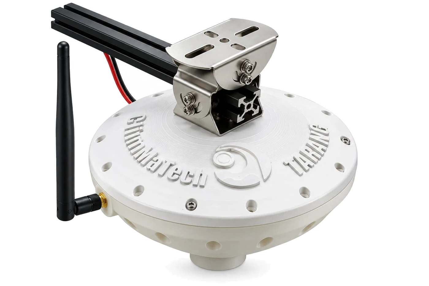
A narrow beam, such as the 8° by 8° beam of Tarang, looks at a small patch of water and gives structures beside the river little chance to return a competing echo. Higher frequencies make a narrow beam possible from a compact antenna, and the choice of frequency, bandwidth and antenna decides the practical accuracy of a level radar [2]. Mounting still matters. Anything inside the beam, and in the sidelobes around it, can return an echo: a bridge pier, a parapet, a cable, a branch.
Why water is an easy target, and how the radar picks the right echo
A flat water surface reflects strongly. With a relative permittivity of about 80, the fraction of power reflected at normal incidence is ((√εr − 1)/(√εr + 1))² = 0.64 [2]. A radar on a bridge sees a rich picture: the water, but also the bridge deck, piers, vegetation and spray. The sensor's firmware has to choose the right echo, and good designs combine several techniques:
- A learned background. The radar records the echoes present when the water is absent or known, and suppresses them.
- Tracking. The water surface moves continuously. A peak that persists and moves smoothly is the water. A peak that appears and disappears is not.
- Range gating. Only echoes within a configured window are considered, which excludes the deck close to the sensor.
- Averaging. Surface waves and ripples spread the echo. Taking many samples per reading smooths them. A radar that samples 1 Hz by default and up to 10 samples a second can average 100 samples in 10 seconds, which reduces random noise by a factor of
√100 = 10. The Central Water Commission's field manual asks a human observer to average a fluctuating surface over about 30 seconds for the same reason [3].
The error budget of an installed station
The accuracy printed on a datasheet describes the sensor under reference conditions. The station has more error sources, and in the field the others are usually larger. An illustrative budget at a 10 m range:
| Source | Illustrative size | Where it comes from |
|---|---|---|
| Sensor, from the datasheet | ±1.0 mm | Electronics and signal processing |
| Air refractive index | ±1.6 mm | Radio waves travel slightly more slowly in humid air. Between dry air at 20 °C and humid air at 35 °C, the refractivity changes by about 160 ppm, which is 1.6 mm over 10 m [4] |
| Surface waves after averaging | ±2.0 mm | Residual movement of the water surface |
| Tilt, 0.5° | ±0.4 mm | A beam off vertical measures d / cos θ, which adds d · (1/cos θ − 1) |
| Mount movement | ±3.0 mm | Bracket flex with wind and heat, settlement of the structure |
| Combined (root sum of squares) | about ±4 mm | √(1.0² + 1.6² + 2.0² + 0.4² + 3.0²) ≈ 4.1 mm |
Two conclusions follow. First, a ±1 mm sensor does not make a ±1 mm station, and it should not be sold or specified as one. A combined ±4 mm is excellent, and fully adequate for flood warning and good rating-curve work. Second, the cheapest improvement is rarely a better sensor. It is a stiffer mount, a plumb mounting and averaging. The same logic applies to a field acceptance test, which should compare the station against a surveyed reference gauge across the working range. The USGS Hydrologic Instrumentation Facility tests radar level sensors in the laboratory over their temperature range and at set distances, for exactly the reason that the lab and the field differ [5].
What matters in the field
- Mount above the highest flood. The sensor must stay above the flood and beyond its minimum measuring distance (the dead zone in front of the antenna).
- Clear view of open water, with nothing in the beam and sidelobes.
- Stable structure, a rigid bracket and a firm deck.
- A known reference, a staff gauge or surveyed benchmark, so the zero can be checked each season.
- Low power. FMCW sensors can be very economical. Tarang draws under 1.5 W when active and 0.2 W on standby, so it runs from a solar panel.
Radar against the alternatives
Ultrasonic sensors also measure from above, but with sound, whose speed changes by about 0.17 % per °C and so needs temperature compensation. Float and pressure sensors sit in the water and are exposed to silt, debris and floods. The comparison is worked through with numbers in radar, ultrasonic, float and pressure sensors compared.
Tarang or Pravaah?
Both measure level with the same 61 GHz FMCW radar. The difference is what else you need to know.
- Tarang is a dedicated level sensor: 61 GHz FMCW, 0 to 50 m (customisable), ±1 mm accuracy, 0.5 mm resolution, an 8° by 8° beam, 1 sample per second by default and up to 10. It suits river gauging points, reservoirs, drains and underpasses. Outputs are 4-20 mA, RS-485, RS-232, SDI-12, LoRa and MQTT, and it works from -40 °C to +70 °C.
- Pravaah adds a 24 GHz Doppler radar that measures surface velocity, so one unit tells you how high the water is and how fast it is moving. The velocity measurement uses a different principle, the Doppler shift, and is explained in surface velocity radar for rivers.
References
- C. Iovescu and S. Rao, The Fundamentals of Millimeter Wave Radar Sensors, Texas Instruments (2017). ti.com.
- The impacts of frequency and antenna selection for free-space radar transmitters, Control Engineering. controleng.com.
- Central Water Commission, India, Gauge and Discharge Measurement Field Manual. cwc.gov.in.
- ITU-R Recommendation P.453, The radio refractive index: its formula and refractivity data. itu.int.
- U.S. Geological Survey, Hydrologic Instrumentation Facility, Laboratory evaluation of a radar water-level sensor. usgs.gov.
Worked values (beat frequencies, resolution, phase sensitivity, beam footprint and the error budget) are computed from the stated relations with illustrative assumptions. They explain how the technique works and are not a specification of any product.